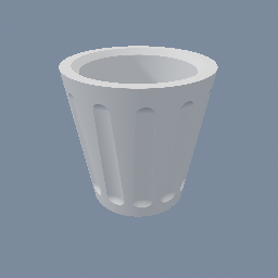
Create a basic vase for 3D printing with SDF
geo/Circle geo/CopyToPoints geo/SDFBoolean geo/SDFTriangulate geo/SDFTube
Documentation / Node reference / geo nodes
Converts SDF geometry to a mesh, a solid, or, from a 2D field, its outline.
Sdf Operations
Samples the SDF field on a grid over its bounds and contours it. SDF objects already display as a raymarch without any node, so reach for this when the geometry itself is needed: to scatter or copy onto, to feed mesh operations, or to export. The grid extends one cell past the bounds on every side, so a shape that reaches the declared bounds still closes. Non-SDF objects are skipped.
**The input's dimension decides what comes out.** A 3D field gives a surface: a manifold solid by default, a triangle mesh (quads under dual contouring) with `as manifold` off. A 2D field gives its zero isoline: a 2D manifold cross-section by default, ready for geo/M2DBoolean and the M2D family, or SEGMENT geometry with `as manifold` off, chained into walk order and oriented with the field's interior on the left, which is what a curve fitter and geo/M2DCreate both want. Cost grows with the cube of the resolution in 3D, the square in 2D.
**If your shape has hard edges, set `method` to dual contouring.** Marching cubes, and marching squares in 2D, cannot produce a sharp edge at any resolution: they are only allowed to put vertices along the grid lines, and a box corner does not sit on one. Raising the resolution shrinks the bevel and never removes it, at eight times the cost per doubling. Dual contouring places one vertex per grid cell wherever the field says it should go, so edges and corners come out crisp at a resolution the other method would round off. In 3D it outputs quads; in 2D it also KNOWS which vertices are corners and publishes them as the `corners` point group.
**Cell size or cell count.** `cell mode` picks which one you give. A COUNT is relative to the shape's bounds: the same 32 covers whatever comes in, so a shape that grows meshes at the same triangle count and a coarser field. A SIZE is absolute: it is a tolerance in world units, and it holds when the shape changes. Size is the default because a part going to a printer is specified in lengths, and the mesh has to be finer than the layer height and the nozzle for the print to land on the model rather than on the meshing. The cap is a cell COUNT either way. A size fine enough to ask for more cells than that keeps its size and meshes only the middle of the shape, cut flat where the cells run out, and the warning says what `resolution maximum` would mesh it whole. `resolution maximum` is that cap for a 3D field: it starts at 256 because a 3D grid costs the cube of it in TIME, and it can be raised when a part genuinely needs the detail.
`isoValue` contours a surface other than the zero set: positive inflates the shape, negative erodes it, in both dimensions and for every output. mat/MeshSDF carries the same param, so the raymarched preview and the mesh can be looked at at the same level.
**To try settings on one detail, turn on `region`.** Only what is inside its box is meshed, so a fine cell size costs a fraction of what it costs on the whole shape. The box comes with a manipulator in the viewport, and `set region from input` resets it to the whole shape. The piece is closed with flat caps where the box cuts it, so it is still a solid.
**If the field came from a volume, `gridFiltering` matters more than the resolution.** A field out of geo/SDFCreate is a grid of voxels, and TRILINEAR reads between them with a gradient that jumps at every voxel face: the mesh gets one facet per voxel and raising the resolution only makes the facets smaller. TRICUBIC reads with a continuous gradient and the faceting goes. It is 64 samples per read against 8, so it is a switch rather than the default, and a tree of analytic primitives ignores it entirely.
**The shading record comes with the mesh.** If the field carries per-region colours (see geo/SDFBoolean), the mesh gets `COLOR`, `ROUGHNESS`, `METALLIC` and `EMISSION` as POINT attributes, sampled at each vertex, which is what multi-colour 3MF and glTF export off an SDF model read. Only the channels that were given a value come out: a channel nobody set, uniform at its default across the whole mesh, is not written, so two coloured spheres mesh to a `COLOR` attribute alone. A field wearing ONE record writes its channels as OBJECT attributes instead, which is the same thing said once. A MANIFOLD output carries the same record: the colours ride inside the solid as vertex properties, survive a geo/M3DBoolean, and come back as those POINT attributes wherever the solid is meshed, under the same rule.
**The 2D output feeds geo/SDFCreate, which is how a 2D field gets a correct INTERIOR distance.** A field built from geo/SDFBoolean is exact outside but only a lower bound inside, with bands following the union's hidden seams. Contour it here, hand the manifold to geo/SDFCreate, and the result is the exact signed distance to this outline on both sides. Use dual contouring on the way if the shape has corners.
| Name | Type | What it does |
|---|---|---|
| method | UInt8 MARCHING_CUBES · DUAL_CONTOURING | Which contourer turns the sampled grid into geometry. Marching cubes, marching squares in 2D, is smooth and predictable and rounds every hard edge off, because it may only place vertices along the grid lines and a corner rarely sits on one. Dual contouring places one vertex per cell where the field actually points, so edges and corners survive; in 3D it outputs quads instead of triangles, in 2D it flags the corner vertices in the `corners` point group. Its faces follow the grid rather than the shape, so run geo/QuadRemeshAuto after it if you want good edge flow as well as sharp edges. |
| isoValue | Float | Contour the surface where the field equals this value instead of its zero set: positive inflates the shape, negative erodes it. A sphere of radius 1 comes out at radius 1.25 at 0.25, and at 0.75 at -0.25. The sampled bounds grow with a positive value, so the inflated surface still closes. It changes what is MESHED, not the field: mat/MeshSDF has the same param for the raymarched form. |
| asManifold | Bool | Output a solid instead of a mesh: .MANIFOLD_3D from a 3D field, so geo/M3DBoolean and the other M3D nodes take it directly, and .MANIFOLD_2D from a 2D one, for the M2D family. The field is clipped to its bounds so the result always closes, and normals are left to whatever triangulates it downstream, since a manifold carries no normals. Per-region colours DO carry: they ride the solid as vertex properties and manifold interpolates them through a boolean. Turn it off for a triangle mesh with normals from the field's gradient, or, from a 2D field, for chained segments. |
| cellMode | UInt8 CELL_SIZE · CELL_COUNT | Whether the sampling grid is given the SIZE of a cell or the NUMBER of them. A count is relative to the shape's bounds, so the same value follows a shape that changes size, holding the triangle count and losing accuracy. A size is a tolerance in world units and holds the accuracy instead, which is what a part headed for a printer needs: the mesh has to be finer than the layer height and the nozzle. The cap is a cell count in both modes. A size that asks for more cells than that is kept, and only the middle of the shape is meshed, cut flat where the cells run out; the node warns with the count that would mesh it whole. `resolution maximum` is that cap in 3D. |
| uniformCellSize | Bool | Keep the grid cells cubic, sizing them from the longest bounds axis. |
| cellSize | Float | Edge length of one grid cell, in world units. It is the accuracy of the result: no feature narrower than a cell survives, and a corner is placed to within one. A shape 1 unit across at 0.05 is 20 cells across. There is a ceiling on cells per axis, `resolution maximum` in 3D and a fixed 1024 in 2D. A size fine enough to exceed it is kept, only the middle of the shape is meshed, and the node warns with the ceiling that would mesh it whole. Turn on `region` to mesh a detail at a size the whole shape could not afford. |
| cellSizePerAxis | Vector3 | Edge length of one grid cell along each axis, in world units. A 2D field reads the x and y components and ignores z, the axis it is flat on. |
| resolution | UInt32 | Number of cells along the longest bounds axis. A 3D field is capped at `resolution maximum`, 256 by default and lower than the 2D ceiling of 1024, because its cost is cubic rather than square; the node warns when it clamps. |
| resolutionPerAxis | Vector3UInt | Number of cells along each axis. A 2D field reads the x and y components and ignores z, the axis it is flat on. |
| resolutionMaximum | UInt32 | Ceiling on the cells per axis for a 3D field, whichever way the grid was asked for. A cell size fine enough to pass it is kept, and only the middle of the shape that this many cells span is meshed, cut flat at the edges, so what you tuned is what comes out and it is obvious the shape is incomplete; the warning says what value meshes it whole. A cell count above it is lowered to it. It exists because a 3D grid is sampled in all three axes, so doubling this multiplies the SAMPLING TIME by eight, and a cell size that looks harmless on a small shape asks for a billion samples on a large one. The memory is a milder story: the grid is sampled and contoured one slab at a time and is never held whole, so what grows is the MESH, with the surface rather than the volume. Raise it when the default 256 is genuinely not enough, and expect to wait. When it bites, the node says so with a warning rather than meshing quietly. A 2D field ignores this and uses its own ceiling of 1024, since a lattice only costs the square. |
| region | Bool | Mesh only what is inside a box, to try settings on one detail without paying for the whole shape. The grid covers the box instead of the whole field, so the same cell count goes much further, and the cell size costs far less. The piece comes out closed, with flat caps where the box cuts through the shape. Drag the box in the viewport, or type its corners. A 2D field uses the box's x and y. |
| regionMin | Vector3 | Lower corner of the box, in world space. |
| regionMax | Vector3 | Upper corner of the box, in world space. |
| setRegionFromInput | Button | Set the box to the bounds of the SDF on the input, so you can shrink it from there. |
| gridFiltering | UInt8 TRILINEAR · TRICUBIC | How a grid field in the tree is read between its voxels. A grid field is what geo/SDFCreate makes from a volume, so a tree of analytic primitives never looks at this. TRILINEAR, the default, is 8 samples per read and has a gradient that jumps at every voxel face, which comes out as one facet per voxel on the meshed surface and, under dual contouring, as cell normals that disagree with each other. TRICUBIC is 64 samples per read and has a continuous gradient, so the faceting goes rather than gets smoothed away by a higher resolution. mat/MeshSDF carries the same param, so the mesh and the raymarched preview can be read the same way. |
| backend | UInt8 CPU · GPU · AUTO | Where the sampling grid is evaluated. CPU walks the field once per grid sample on the thread pool. GPU evaluates the same field as a compute shader on the graphics card and reads the samples back. AUTO, the default, picks between them on the SIZE of the grid, at the number of samples given by `samples count threshold`. Size is what decides it because the card costs a fixed amount before it evaluates anything: it has to be handed the field, dispatched, and read back, which is around half a millisecond whatever the grid. A coarse grid is done on the CPU in less time than that, so a small mesh is faster without the card and a fine one is several times faster with it. Only the SAMPLING moves: the contouring, the normals and the per-vertex colours are the same code on both. Where the card cannot be used it falls back to CPU: in the browser, in a build without compute shaders, and on a field the shader builder refuses. Ask for GPU by name and the node says so with the reason; under AUTO a build that has no card at all is silent, since nothing was asked for. The mesh is the same either way, only the cost is not. |
| samplesCountThreshold | UInt32 | The grid size AUTO switches to the GPU at, counted in samples rather than cells. At or above this many samples the field is evaluated on the graphics card, below it on the thread pool. The default of 20000 is measured: it is roughly where the card's fixed cost, about half a millisecond to hand over the field, dispatch and read the values back, stops being more than the whole CPU walk it replaces. Lower it if your fields are deep, since a tree of many primitives under smooth booleans pays that cost back far sooner than a lone sphere does. Only read when `backend` is AUTO. |
Scenes you can open in the editor that teach this node.
Create a basic vase for 3D printing with SDF
geo/Circle geo/CopyToPoints geo/SDFBoolean geo/SDFTriangulate geo/SDFTube
This page is generated from the engine, so it describes the release you can download. The same text is in the editor's Help panel next to the node itself.